
 English
 Türkçe
Hot sale 5B2 58425JOH HYDRAULIC GEAR PUMP | Partsdic®
Time: 2024-08-20 17:00:04
Click:
hot-sale-5b2-58425joh-hydraulic-gear-pump-partsdic
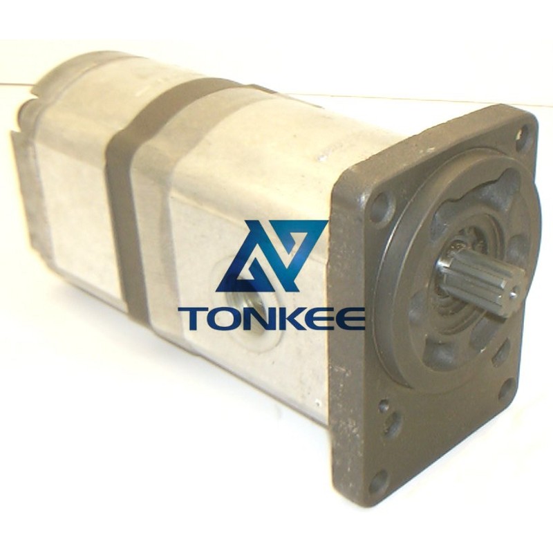
Design: The 5B2 58425JOH Hydraulic Gear Pump follows a gear mechanism, which consists of two meshing gears—a driving gear and a driven gear.
These gears create a sealed cavity that moves hydraulic fluid. Materials: The pump is typically constructed from high-quality materials such as cast iron or aluminum to ensure durability and resistance to corrosion. Flow Rate: The pump has a specified flow rate, measured in gallons per minute (GPM) or liters per minute (LPM), indicating the volume of hydraulic fluid it can deliver under certain conditions. Pressure Rating: It comes with a pressure rating, usually measured in pounds per square inch (PSI) or bar, indicating the maximum pressure it can generate in the hydraulic system. Mounting Options: The 5B2 58425JOH Hydraulic Gear Pump offers various mounting options, including flange or bracket mounting, making it adaptable to different system configurations. Components: Gear Set: The heart of the pump consists of two interlocking gears—a driving gear (usually the larger one) and a driven gear. As they rotate, they create chambers of varying volume, which forces hydraulic fluid to flow from the inlet to the outlet.Inlet and Outlet Ports: These are the points where hydraulic fluid enters and exits the pump.
Proper plumbing and connection of these ports are crucial for the pump's operation. Housing: The gears and other internal components are enclosed in a housing that maintains the integrity of the hydraulic system and prevents leakage. Shaft: The shaft connects the driving gear to the external power source, such as an electric motor or an engine. It transfers mechanical energy to the gear set, initiating the fluid movement. Working Principles: When the hydraulic gear pump is in operation, the driving gear is connected to an external power source and starts to rotate. As the gears mesh, they trap hydraulic fluid in the space between their teeth. As the gears continue to rotate, the volume of these chambers changes, causing the trapped fluid to be displaced. Inlet Stage: Initially, one gear tooth creates a void, and hydraulic fluid is drawn into this void through the inlet port due to the pump's vacuum effect. Compression Stage: As the gears rotate further, the trapped fluid is compressed, increasing its pressure. This pressurized fluid is then forced towards the outlet port. Outlet Stage: Finally, the fluid is expelled through the outlet port at a high pressure, ready to power hydraulic actuators, motors, or cylinders in the system.
点击右上角
分享给朋友吧


 Long by picture save/share
Follw us
点击右上角
分享给朋友吧
Any references to trademarks, names, descriptions, numbers, and symbols on our website are utilized for reference purposes only. All trademarks pertaining to original equipment manufacturers are duly registered trademarks of the respective original equipment manufacturers. Our website explicitly disclaims any direct association or affiliation with the manufacturers listed. The use of manufacturers' names and descriptions is strictly for reference purposes and does not imply any endorsement or sponsorship.
点击右上角
分享给朋友吧
© 2024 swingmotor.com
